ERATZ Engineering
VeraCAD
Project work shown in pictures
CAD import
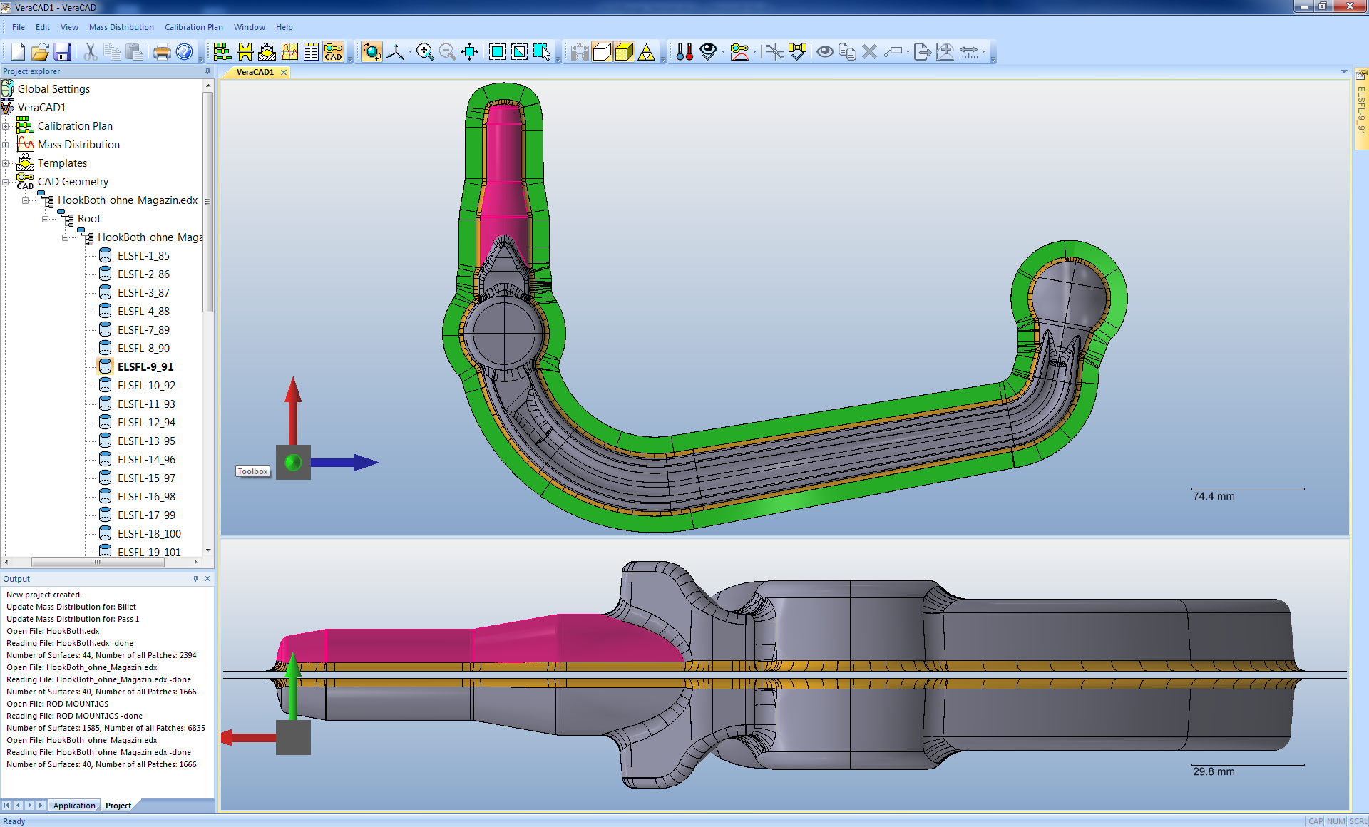
VeraCAD imports the 3D geometry of a forging part via standard interface (IGES, VDAFS or STL) from any CAD system.
Derive mass distribution
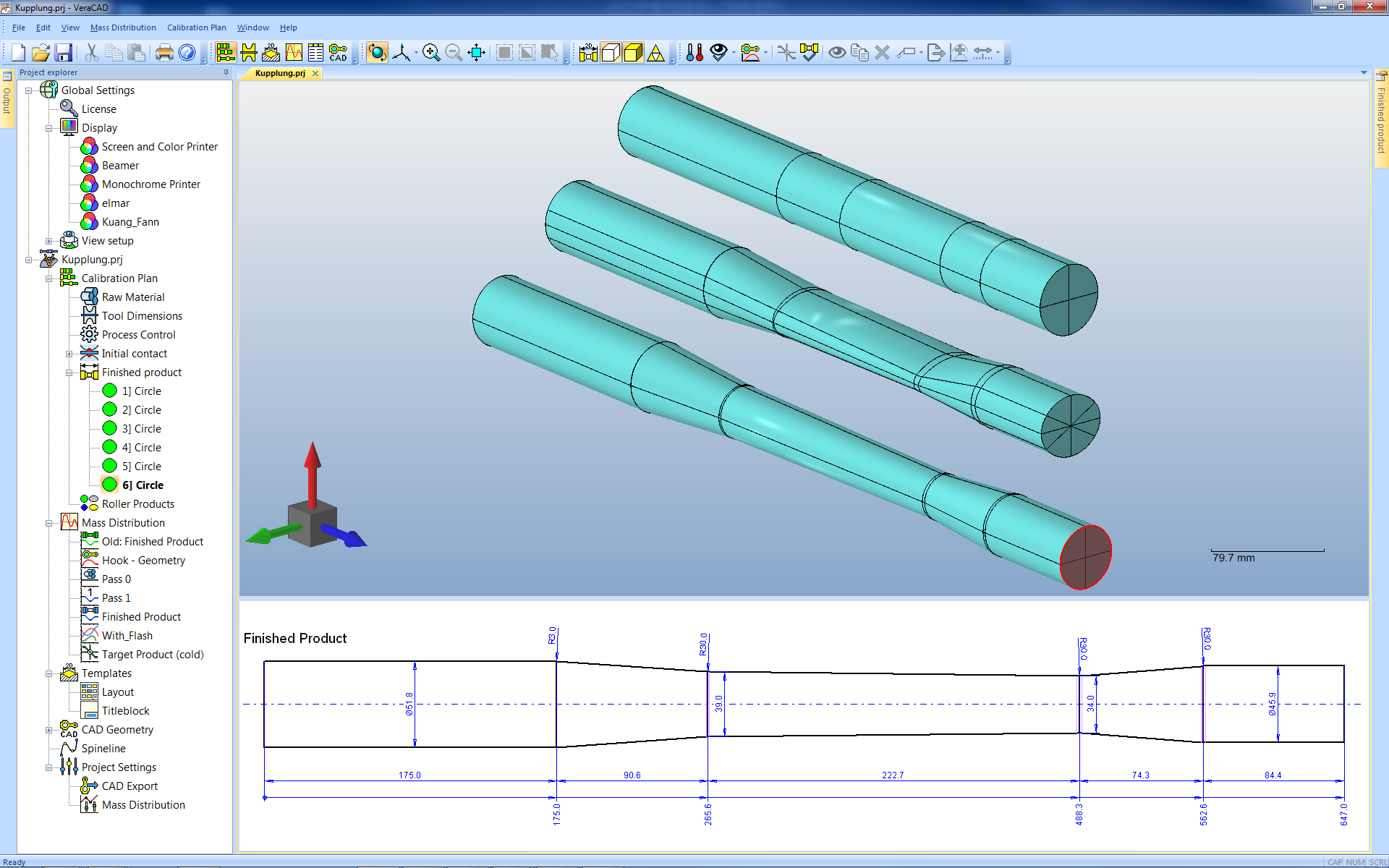
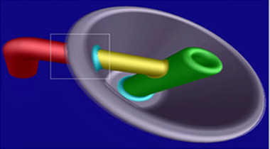
First a spine line is digitized (yellow line). Along this line VeraCAD calculates a mass distribution diagramm. The final roller part based on the mass distribution is created automatically (blue line).
Create calibration plan
Depending on total reduction the calibration plan has 2 passes. VeraCAD makes proposal of cross-section shape and reduction rates. More technology parameters can be supplied in the property grid window.
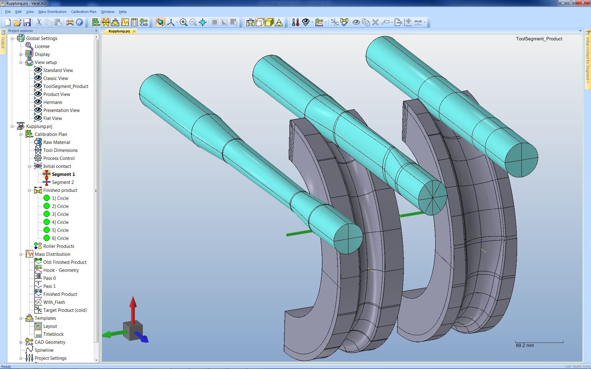
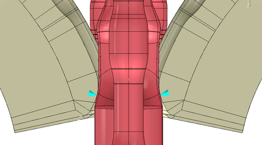
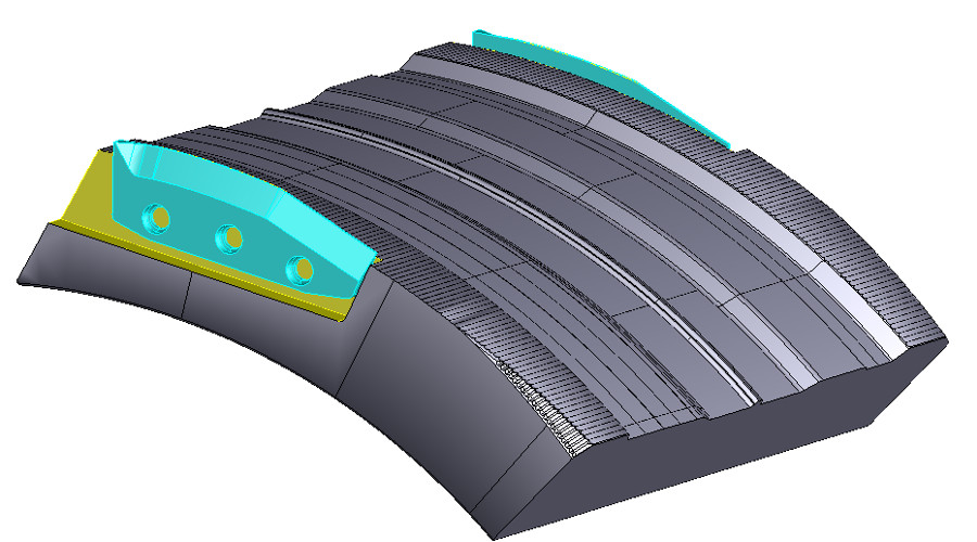
3D geometry of tool segments
After any parameter change, roller products and tool segments are updated immediately. These are suitable both for CNC-milling as well as for a FEM simulation. The CAD export is done via a standard interface.
2D technical drawing
A fully dimensioned technical drawing exists for each roller pass, tool segment and for the calibration plan.
Menu
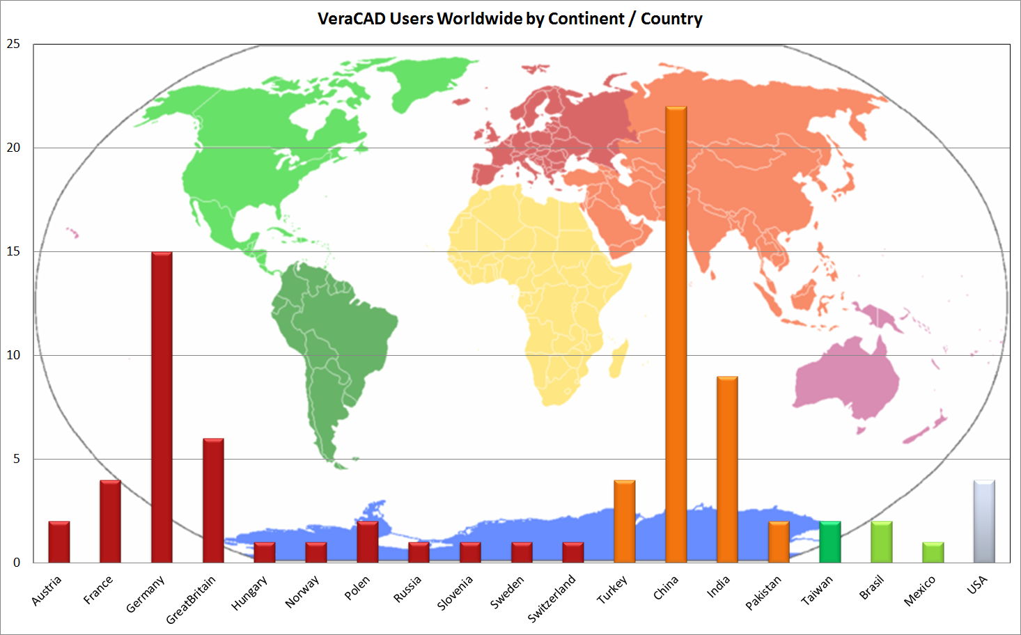
References
Germany- Bharat Forge Aluminiumtechnik GmbH Brand-Erbisdorf
- Daimler AG
- Frauenthal Powertrain GmbH
- Erdmann Unternehmensgruppe Hammerwerk Haspe
- Frauenthal Powertrain GmbH
- Hirschvogel Automotive Group
- KMS Gesenkschmiede Deutschland
- Otto Fuchs Metallwerke GmbH
- Schmiedetechnik Plettenberg GmbH & CO.KG
- PSW Schmiedewerk GmbH
- SCHMIEDAG GmbH
- Schöneweiss & Co. GmbH
- Schürfeld GmbH
- Schuler Pressen GmbH
- SMS group
- Thyssen Krupp Gerlach GmbH
- Baicheng Zhong Yi Precise Forgings (VRC)
- Bharat Forge Limited (IND)
- Bharat Forge Kilsta (SWE)
- Dana Spicer Europe Ltd (GB)
- DANA INDUSTRIAS LTDA (BRA)
- Dandong WuYiba (VRC)
- Dong Feng Motor Cooperation (VRC)
- Forges de Courcelles (FRA)
- FORJA de Monterrey (Mex)
- Happy Forging (IND)
- IMATRA Scottish Stamping (GB)
- IMATRA Tooling AB (SWE)
- John Stokes Forgings Ltd. (GB)
- Kongsberg Automotive (NOR)
- Mannan Shahid Forgings Ltd. (PK)
- Mahindra CIE Automotive Ltd. (IND)
- MMForgings Ltd. (IND)
- Pankl Schmiedetechnik GmbH (A)
- Peddinhaus Modern Technologies, LLC (USA)
- PSA Peugeot Citroën (FRA)
- PUNCH Precision Detva S.R.O (SVK)
- Rába Vehicle Ltd (Hungary)
- Ramkrishna Forgings (IND)
- Sansera (IND)
- Setforge Estamforge - Farina Group (FRA)
- Strojmetal Aluminium Forging s.r.o. (CZE)
- Thyssen Krupp Brazil (Bra)
- Thyssen Krupp Crankshaft Company (USA)
- Thyssen Krupp Mexiko (MEX)
- UEF Automotive Neptune Works (GB)
- University of Ulsan (KOR)
- UNIOR (SLO)
- Walor Bogny (FRA)
- Zimmer GmbH (CHE)
Software
More
Imprint
ERATZ EngineeringHerrmann Eratz
Kirchhörder Str. 94
44229 Dortmund
Germany
Phone +49 (0)231 72 73 290
Fax +49 (0)231 72 73 291
E-Mail: he@eratz.de
© ERATZ Engineering
